- Concrete Paver Information
- Concrete Paver Pictures
- Patio Pavers
- Driveway Pavers
- Pool Deck Pavers
- Sidewalk & Walkway Pavers
- Porous and Permeable Concrete Pavers
- Installing Concrete Pavers
- Pavers Installation: Step-by-step overview of base compaction and mechanical installation
- Pricing of Concrete Pavers
- Paver Thickness & Specifications
- Other Resources
- Find Products: Pavers & Supplies
Permeable and Porous Concrete Pavers
The terms permeable and porous pavers refer to pavers which allow water to percolate through them.
Permeable pavers present a solid surface but allow natural drainage and migration of water into the earth by permitting water to drain through the spaces between the pavers.


Porous pavers, on the other hand, present a surface with "holes" which can be filled with vegetation or aggregate depending upon the need. Porous/permeable pavers provide the same advantages as traditional concrete pavers, including resistance to heavy loads, flexibility of repair, low maintenance, exceptional durability, and high quality.
Uses For Permeable Concrete Pavers Driveways, Patios and more
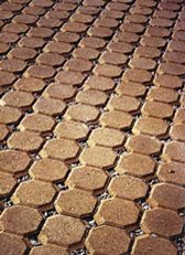
This type of interlocking paver can support heavier vehicle loads and can be installed in running-bond, basket weave, and herringbone patterns.
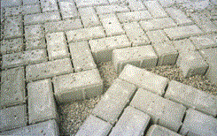
These heavy duty permeable pavers were used for a container port application in Latin America.
Porous Concrete PaversExamples
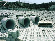
Pavers such as Turfstone by Uni-Group U.S.A. are used for overflow parking, emergency access areas, embankments spillways and other environmentally sensitive areas. Pavers can be filled with vegetation or aggregate depending upon use.
Typical Applications
Vehicles
Here are some typical applications for permeable / porous pavers at areas used by vehicles:
- RV access and boat parking areas
- Residential driveways
- Overflow parking
- Fire lanes
- Emergency vehicle access lanes
- Golf cart and pedestrian paths
- Design parking areas with water retention in mind
- Drivable green surface
- Emergency and Fire Vehicle Access
Porous pavers allow ground cover to be planted and can provide emergency vehicle access and landscaping at the same time as controlled runoff.
The porous pavers allow the area to resemble an unpaved area yet provide many of the same benefits of paving.
Landscaping
Here are some of the ways porous pavers can be used to improve elements of the landscape:
- Placement around trees can allow water and elements to get to tree roots.
- Porous pavers permit planting of grass or other vegetation while providing a driveable surface.
- Porous pavers can be used for soil reinforcement and stabilization
- Can reduce turf-wear problems in high foot traffic areas
- Use porous sections beneath roof overhangs to help break force of water and prevent erosion.
Land Use and Planning
In some communities, calculation of open space permits an allowance for use of permeable decorative pavers.
Use as a green alternative to asphalt pathways.
Reduce amount of impervious surfaces in a project.
In some communities, when a second parking space is not covered, it may count as a landscaped area if paving uses permeable pavers.
Stormwater and Erosion Control Applications
Permeable or porous pavers on your project can have a positive impact on the following issues:
- Use infiltration to reduce stormwater runoff that leaves parking lots
- Increase stormwater storage
- Reduce thermal loading on surface waters
- Reduce pollutants reaching surface waters
- Groundwater recharge/storage
- Reduce down-stream flooding
- Erosion control of stream beds and river banks
Erosion Control and Groundwater Recharge Basins
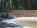
Use of porous pavers can be part of a stormwater management control program and groundwater recharge or storage system. Downstream flooding and erosion of banks and stream beds can be lessened. In addition, on-site percolation of rainwater lessens thermal impacts on streams and can mitigate pollution effects upon adjacent waters.
Financial Benefits
Here are some of the financial benefits when permeable or porous pavers are used on your project:
- Reduce amount of drainage and runoff caused be your project.
- Reduce storm water retention systems
- Can be laid in remote areas without normal construction plants
- Maximize land use by using the permeable pavement as a rainwater retention facility
- Quick and easy removal for underground utility repairs
How They Resist Vertical, Horizontal, and Rotational Forces
Basically, permeable or porous paving resists forces by creating an interlock between pavers.
Vertical loads are transferred to surrounding units by the sand in the joints.
Horizontal loads from braking and accelerating are handled via laying patterns and paver shapes that allow dispersion of forces on two axes. The Herringbone pattern provides a particularly effective interlock.
Rotational loads can be resisted by pavers that are: sufficiently thick, placed close enough together, and have a confining stationary edge.
Specification Guide's For Developing a Scope of Work
General Topic Specifications
Note: This specification guide is excerpted from Uni-Group USAs guide. This section is intended only to give an insight into items to include when developing a scope of work for a project.
General topics to include in specifications are:
Quality Assurance
- Experience installation crew on similar size and cost projects
- Bonded and licensed contractor
Submittals
- Drawings and product data
- Full size samples for color and shape
- Sieve analysis for grading of bedding and joint sand
- Test results showing compliance to ASTM C936 or other applicable code
- Manufacturers certification of pavers having passed ASTM standards
- Layout, pattern, how fixtures handled and other details
Mock-ups
- Install a large enough paver area to determine surcharge of bedding sand layer, joint sizes, lines, laying patterns, colors, and texture of project. (2m x 2m)
- Note: This area should provide the basis from which work will be judged and will be incorporated into the project.
Delivery, Storage, and Handling
- Pavers to be delivered to site in cubes capable of transport by fork or clamp lift.
- Sand to be covered to prevent exposure to rain or wind
- Deliveries and paving schedule to minimize impact on access to buildings adjacent to project
Material Issue SpecificationsPorous Concrete Pavers
Note: This specification guide is excerpted from Uni-Group USAs guide. This section is intended only to give an insight into items to include when developing a scope of work for a project.
Pavers
- Specify if to be mechanically or manually laid. (Mechanically laid pavers have a spacer bar)
- Specify manufacturer, name, address, phone
- Specify paver model to be used, product name an dimensions including thickness, color (s) or blends available locally
Bedding & Joint Sand
- Screenings and stone dust can be unevenly graded and have material passing No. 200 sieve and should NOT be used. Do not use masonry sand.
- For vehicular traffic pavements, use sands that are as hard as practically possible.
- Contact the paver manufacturer for information on bedding sand durability.
- Sieve according to ASTM C136
- Joint sand should not be used for bedding sand
Edge Restraints
- A wide variety of edge restraints are available and range from timber to plastic to concrete to steel or aluminum as well as cut stone
- Specify type, manufacturer (if applicable) and standards.
Project Installation Issue Specifications
Note: This specification guide is excerpted from Uni-Group USA's guide. This section is intended only to give an insight into items to include when developing a scope of work for a project.
Examination:
- Verify subgrade preparation, compacted densities and elevations conform to specifications.
- Note: Finished grade may be inch above final elevation after compaction. This is to allow for minor settling.
- If geotextiles used, verify placement conforms to specifications and drawings.
- Verify aggregate base materials, thickness compaction, surface tolerances and elevations conform to specifications.
- Compaction should conform to ASTM D698 for pedestrian areas and residential driveways, ASTM D 1557 for heavy vehicular traffic.
- Attention should be paid to stabilization of subgrade if upon weak or saturated solids.
- Local aggregate base materials should conform to those used for highway flexible pavements or ASTM D2940.
- Aggregate base should be spread in uniform layers not exceeding 6 inches in thickness and recommended base surface tolerance should be +/- 3/8 over a 10-ft straight edge.
- If geotextiles used, base preparation, surface tolerances and elevations should conform to specifications
- Mechanical tampers recommended for compaction of soil subgrade and aggregate base.
Installation:
- Bedding sand: Do not use to fill in depressions in the base surface. Spread evenly over base course and screed to required thickness, typically a nominal 1 inch, not to exceed 1 inch thick).
- Pavers are to be free of foreign materials before installation and installed in pattern per drawings, maintaining straight lines.
-
Joints between pavers to be per manufacturers design requirements (typically 1/16 to 3/16 inch wide but may need to be wider).
- Fill gaps at edges of paved areas in accordance with manufacturers or designers requirements
- Vibrate pavers, sweep dry joint sand into joints and vibrate until full repeat as necessary. Do not vibrate within 3-ft of the unrestrained edges.
- Surface elevation of pavers shall be 1/8 to inch above adjacent drainage inlets, concrete collars or channels.
Mechanized Installation
Mechanized installation, specialized paver installation equipment speeds construction time by installing approximately one square yard (one square meter) of pavers at a time in rapid succession.
For more on mechanized installations, click here
Field Quality Control:
- After removal of excess sand, check final elevations for conformance to drawings.
- Upon completion of work, remove any debris, surplus material, and equipment from site.
Maintenance of Porous Concrete Pavers
If permeable/porous pavers are selected for water management purposes, a reduction in perviousness can occur over time, due either to accumulation of fine particles or organic growth.
Cleaning with commercial street sweeping/vacuuming equipment is recommended by some manufacturers on an approximate 4-year cycle. Additional aggregate fill material can be added to drainage openings at joints or paver voids as required.
Technical Information
Basics of Hydraulic Design
Two goals for alternative pavements are to allow water to pass through top layers easily and be able to store water in the gravel layer temporarily. An integral part of the design involves determining not only how much water can be stored in the system, but also how fast it will drain (exfiltrate) from the system. The following is an approach to achieving these goals.
Select the design storm and associated likely rainfall usually a one or two-year return period.
Determine the storage capacity of the permeable paving system using the depth of gravel and void space between the stones. Your gravel supplier can usually provide this information.
Compare rainfall and storage capacity. If storage capacity is greater than expected rainfall from design storm, design is adequate to this point.
Determine desired percolation capability of underlying in-situ soil. If it would take longer than 48 hours for the stored water to drain into the soils, this may not be a suitable project for stormwater control. 20 hours is suggested for design exfiltration purposes.
Calculate actual amount of time required for water to drain from gravel.
Compare design exfiltration time to actual drawdown time.
Note: Further information on hydraulic design for permeable pavements can be found from manufacturers and at the North Carolina State University site: North Carolina State University permeable paver information.
Design Software
Uni-Group USA offers a software design program which uses the US EPA Stormwater Management Model (SWMM 4.30) for the design of permeable pavement.
It allows the user to develop a simple model of permeable pavement design, run the model with a specified design storm, and analyze the results. Model results include graphs of the input function (design storm), surface runoff (if any), depth of water in the base material, and drainage of the base material for the duration of the model run. It was developed by Computational Hydraulics, Int.
Further information may be found at: http://www.uni-groupusa.org/software.html
